


The Siemens S7-1200 series PLC covers various displacement command functions, specifically including left and right displacement operations, as well as cyclic left and cyclic right displacement operations.
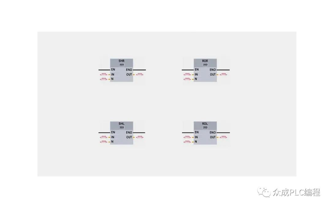
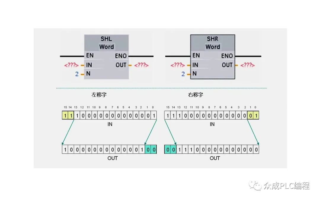
The main function of these displacement instructions is to adjust the bit sequence in the input parameter IN and pass the adjusted result to the output parameter OUT. The number of displacement bits is specified by the parameter N. This feature supports a wide range of data types, including Byte (BYTE), Word (WORD), and Double Word (DWORD). During the displacement process, any position that is cleared will automatically fill with 0.
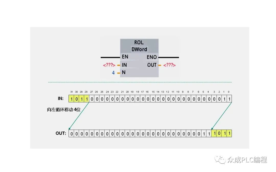
The cyclic displacement instruction uses a cyclic approach to move the bit sequence in the input parameter IN, and the result will also be passed to the output parameter OUT. The number of digits for cyclic displacement is also set through parameter N. The notable feature of this instruction is that the bit data moved from one side of the target value will be looped to the other side, ensuring that the original bit value will not be lost throughout the process.
Below, we will demonstrate the practical application of these instructions through an intuitive example. When I1.2 is triggered, the data in MB100 will move two bits to the left and the result will be stored in MB200; When I1.3 is triggered, the data in MW100 will move two bits to the right, and the result will be stored in MW300.
1、 Programming
Firstly, open OB1 in the project view.
Subsequently, drag the left shift instruction from the instruction tree to program segment 1 and set the data type to bytes. At the enable end, we insert the normally open contact I1.2. Then, set the IN parameter to MB100, N parameter to 2, and OUT parameter to MB200.
Similarly, we will drag the right shift instruction to program segment 2 and set the data type to word. At the enable end, we insert the normally open contact I1.3. Next, set the IN parameter to MW100, N parameter to 2, and OUT parameter to MW300.
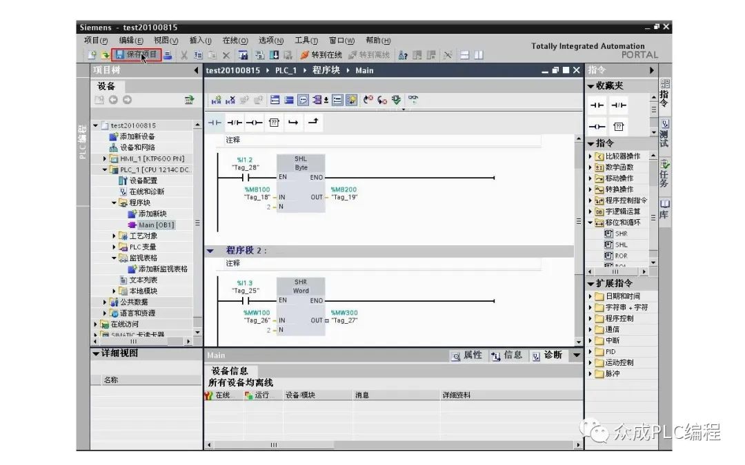
After completing the above settings, save the project.
2、 Program Compilation and Download
Select the program block in the project tree, click the download button, and download the written program to the PLC.
3、 Program operation monitoring
Click the "Go Online" button to open the monitoring table folder.
In this folder, we create a new monitoring table and enter the addresses MB100, MB200, MW100, and MW300, setting the display format to binary.
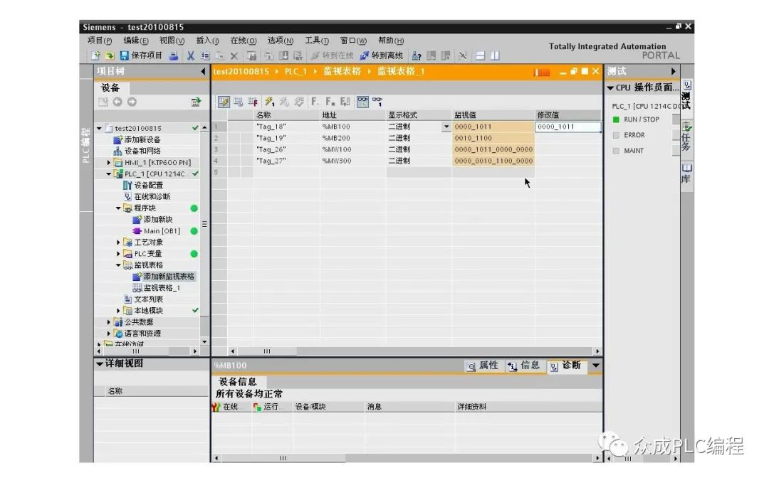
Finally, by clicking the monitoring button, we can observe the running status of the program. For example, we can first modify the value of MB100 to 01011, and then press I1.2. At this point, we will find that the value of MB200 has changed to the result of MB100 being shifted two places to the left; Similarly, when we press I1.3, the value of MW300 will also change to the result of MW100 being shifted two places to the right.