


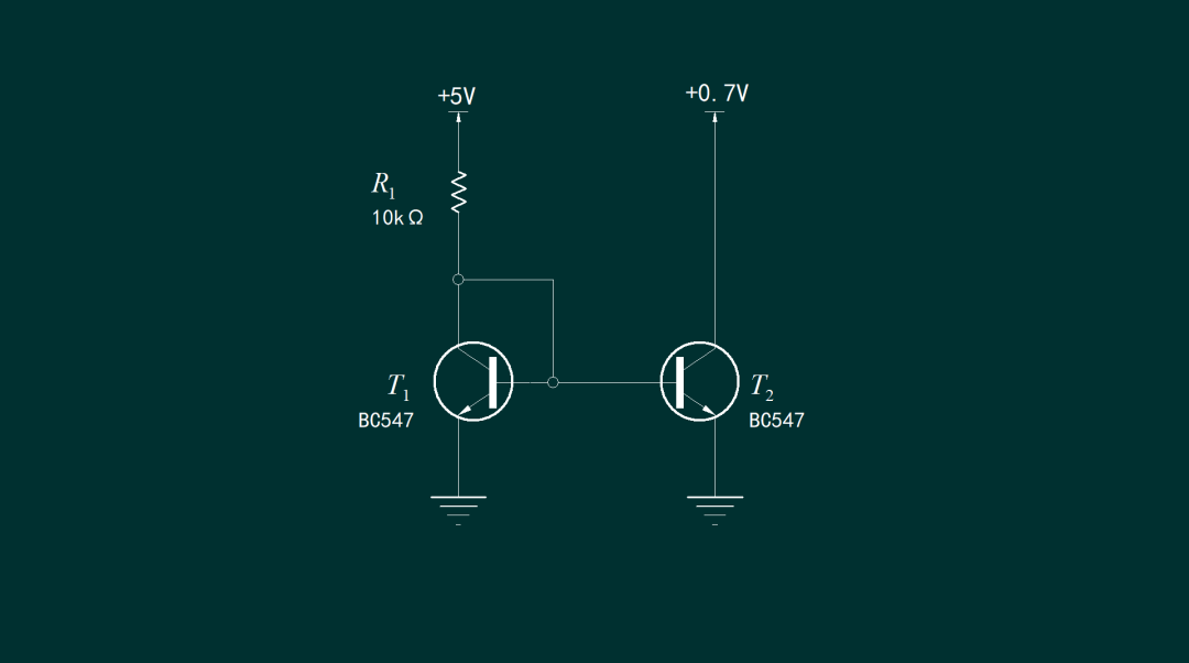
1、 Current mirror circuit
This current mirror circuit requires the two collector currents to be the same when the two transistors are completely symmetrical. Next, let's verify again through experiments the factors that affect the different currents on both sides. Fix the voltage of the left reference circuit. The working voltage of T2 on the right is set to 0.7V, so that it is as close as possible to the collector voltage of T1 on the left. Calculate the reference current using the voltage on the standard resistor 10k, and measure the collector current of T2 using a digital multimeter DM3068. Check the numerical relationship between the currents on both sides.
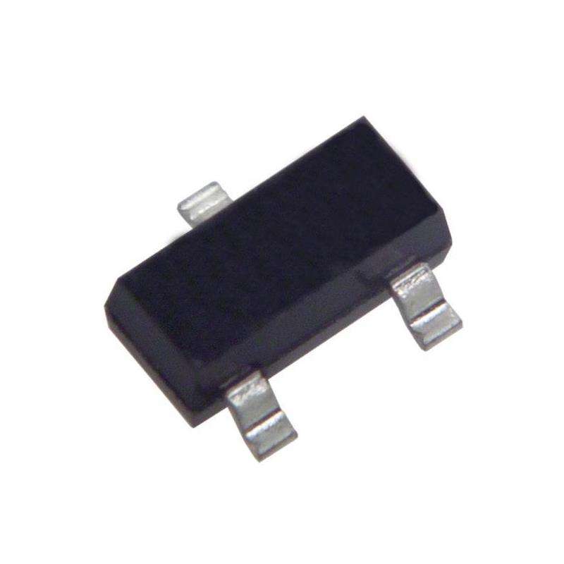
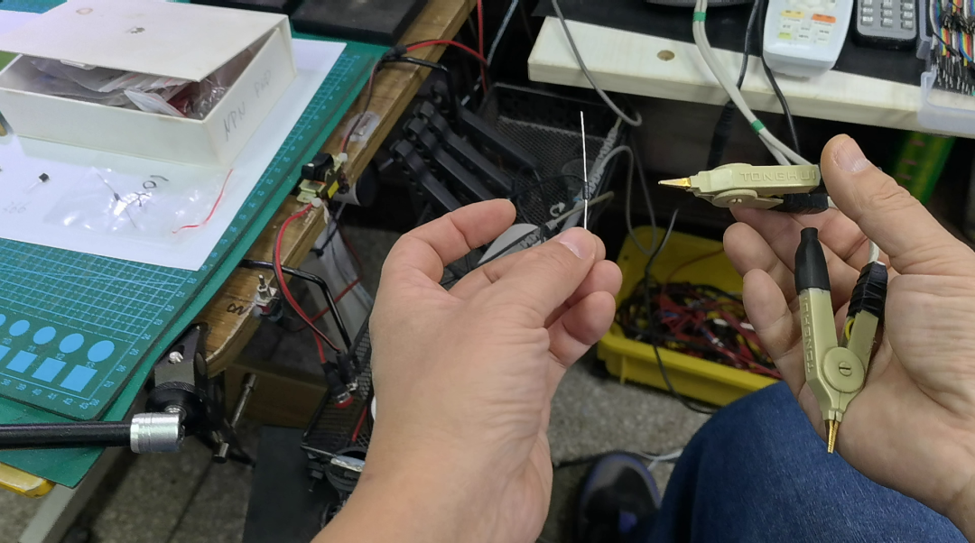
2、 Transistor
Select three BC547 transistors and use a transistor assistant to measure their current amplification factor. The beta of the first transistor is equal to 310. Measure the second transistor, which corresponds to β=340. Measure the third transistor. Its current amplification coefficient is the highest, at 366. Select a high-precision resistor as the load for T1, measure its resistance value, and its corresponding resistance is 10.022k Ω.
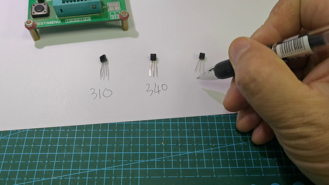
| The first transistor | Second transistor | Third transistor (C945) |
|---|---|---|
| 310 | 340 | 366 |
Load resistance of transistor T1:
R1:10.022kΩ
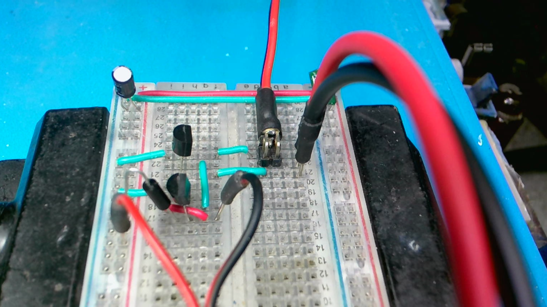
Next, build a test circuit on the breadboard to see if the amplification factor of the transistor current is the main reason affecting the current on both sides.
3、 Current amplification factor
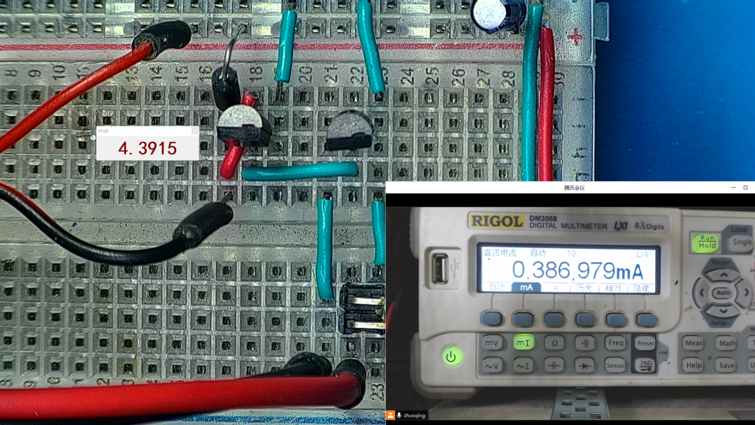
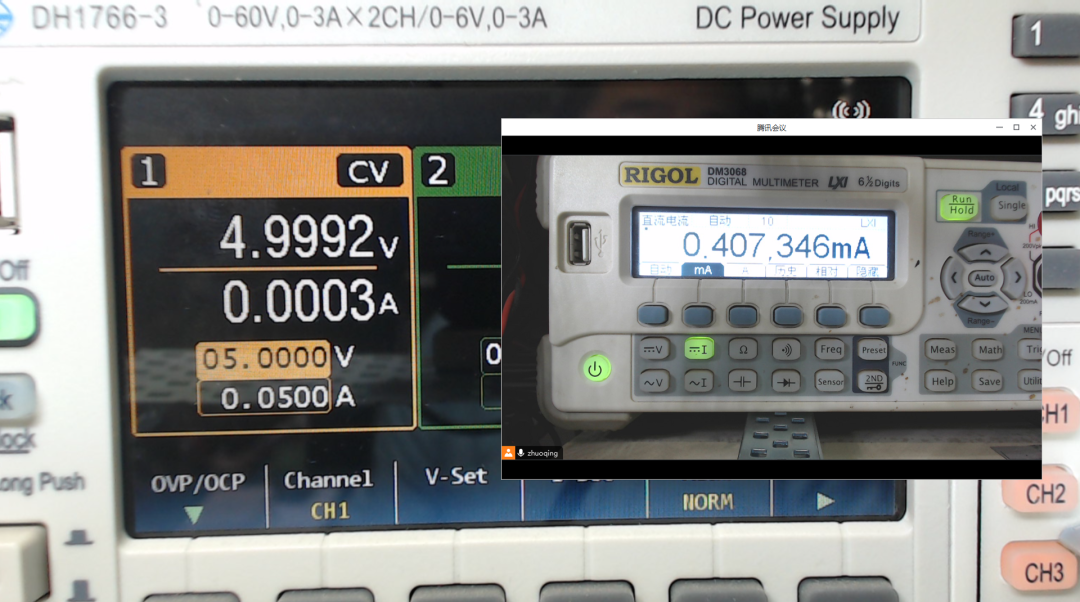
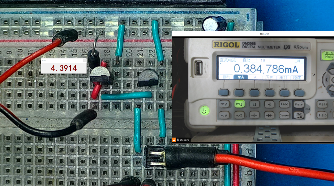
Build a test circuit on a breadboard. Firstly, select two transistors, both of which have a beta value of around 310. The reference current is 5V voltage passed through a standard resistance of 10k ohms to the T1 transistor. Measure the voltage value on the resistance using a digital multimeter and obtain the reference current in reverse. Use a digital multimeter to directly measure the output current. After power on, the voltage on the 10k ohm resistor is 4.3915V, corresponding to a reference current of 0.439mA. The output current is 0.387mA. It can be seen that there is a significant difference between them. At this time, the operating voltage of the output transistor is 0.7V. Raise it to 5V. At this point, the output current rises to 0.407mA. Still smaller than the reference current. Reduce the operating voltage of the output transistor to 0.7V, and the corresponding output current will slightly decrease. Through this test, it has been demonstrated that the factor affecting the output current of the current mirror is not the current amplification factor. It also has little to do with the working voltage.
Next, touch the output transistor with your hand to increase its temperature, and you can see that the output current gradually rises to 0.44mA. When the hand is moved away, the temperature of the transistor decreases. When the temperature of the transistor decreases again, the output current returns to the original 0.386mA. Conversely, if the hand touches the reference current transistor, the output current decreases. After removing the hand, the output current is restored.
This article tests the circuit stability of a current mirror composed of two discrete transistors. I never expected that the biggest factor affecting the output current would be the temperature of the transistor. If the temperature of the output transistor is high, the output current will increase. If the temperature of the reference current transistor increases, it will cause a decrease in output current. I really didn't expect the significant impact of this temperature on the circuit.